
42
Guardian Air/Vacuum Valves
for Vacuum Protection
in Drip Irrigation
In drip irrigation, especially subsurface drip irrigation,
vacuum prevention is essential, even at very low negative
pressure, for the prevention of suction of dirt through
drippers, as well as for the prevention of damage to piping
and accessories.
There are three major causes for the formation of vacuum
cavities in manifolds from which dripper laterals emanate
(distribution manifolds)
and in manifolds to which they
drain
(collection manifolds)
.
1. At sudden pump stoppage or valve shut-off, water
column separation occurs after the inline isolating
valve and at peaks, because water supply is suddenly
VWRSSHd \HW WKH H[iVWinJ ZDWHU PDVV FRnWinXHV WR ÁRZ
driven to the forces of inertia. Vacuum cavities are, thus,
developed, exerting negative pressure and suction.
2. At system drainage, if air is not admitted at the rate water
is drained, vacuum cavities form, exerting negative
pressure and suction. In extreme cases, this can result
in pipe or accessory collapse.
3. At pipe or accessory burst
EOind Áanges risers Rr Rn
Oine isROating YaOYes EreaNing RII IRr instanFe
, water is
dUDinHd VRPHWiPHV DW JUHDW ÁRZ UDWHV. ,I ZDWHU VXSSO\ iV
slower than the rate of drainage, and air is not admitted
into the pipe, vacuum cavities form, which cause suction
and, sometimes even pipe or accessory collapse.
)RU WKH DERYH UHDVRnV ODUJH RUiÀFH NinZZHWiF DiU/YDFXXP
valves are required:
a. After inline isolating valves at valve heads, and in
distribution and collection manifolds,
b. At peaks along distribution and collection manifolds,
c. On tops of risers at the ends of the manifolds.
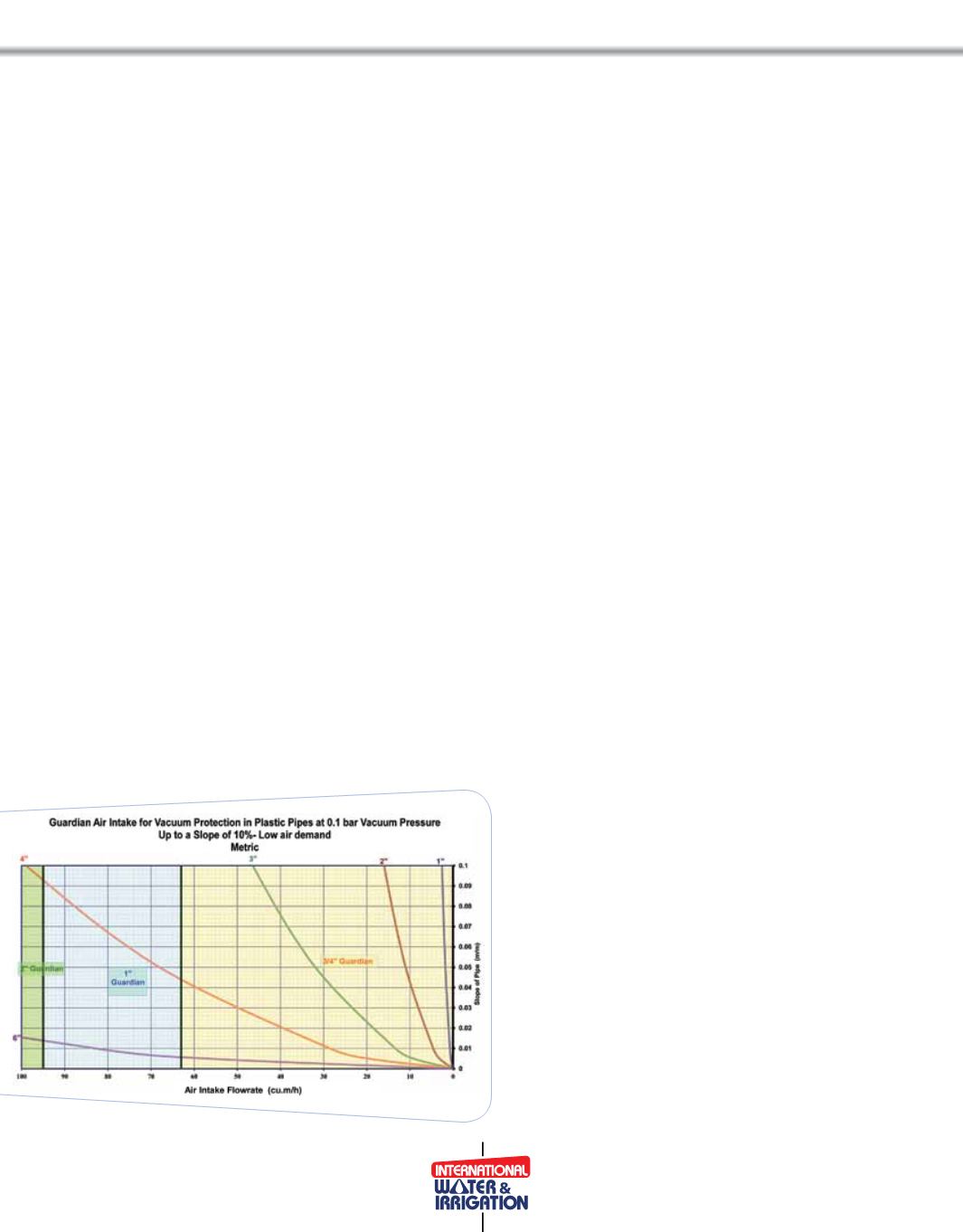
Sizing of the air valves should be determined according to
WKH PD[iPXP ZDWHU ÁRZ UDWH DW ZDWHU FROXPn VHSDUDWiRn.
•
,I WKH ÀHOd iV UHODWiYHO\ ÁDW ZiWKRXW VHUiRXV HOHYDWiRn
diIIHUHnFHV Dnd/RU ViJniÀFDnW VORSHV \HW WKH RSHUDWinJ
ÁRZ UDWH iV ViJniÀFDnW DiU YDOYH Vi]inJ VKRXOd EH
dHWHUPinHd DFFRUdinJ WR WKH RSHUDWinJ ÁRZUDWH. 7KH
reason for this is that at sudden valve closure, the water
FROXPn FRnWinXHV ÁRZinJ DW WKH RSHUDWinJ ÁRZ UDWH DW
least for a very very short time. Thus, air intake should
EH HTXDO WR WKH RSHUDWinJ ÁRZ UDWH.
•
,I WKH ÀHOd KDV D YDUiHd WRSRJUDSK\ ZiWK diIIHUHnFHV
in HOHYDWiRnV Dnd/RU ViJniÀFDnW VORSHV DiU YDOYH Vi]inJ
should be determined in accordance to the maximum
dUDinDJH ÁRZ UDWH DW FRnWUROOHd dUDinDJH RU EXUVW
the higher RI the tZR
.Air intake should be equal to
PD[iPXP dUDinDJH ÁRZ UDWH.
To prevent suction even at very low negative pressures,
air intake should be determined at low negative pressure,
say 1.45 psi
(0.1 bar)
.
Naftali Zloczower,
B.Sc.C.E., A.M.ASCE, Licensed Civil Engineer (Israel), A.R.I. Flow Control Accessories Ltd.


